Sunday 30 October 2011

13. Distributor and Fuel pump and accessories.

We are now going to fit the Distributor, Fuel pump, oil lines and Generator stand.

Fuel Pump

Install the fuel pump before the fuel pump shroud is installed. There are 2 different Fuel pumps, an earlier A/B larger pump and a smaller C/912 type pump.
The later pump can be used on earlier engines.


Parts of the earlier A/B pump, Pump, aluminium intermediate flange and Bakelite spacer


On the earlier pumps there is a Bakelite insulator block that goes between the pump and the third piece as in the above photograph.

There is some excellent information on this link about both types of pumps.


Clean the intermediate flange and take a new gasket and insert the aluminium intermediate flange into the third piece of the engine with a new gasket between it and the case. You need to slide the flange over the 2 case studs. If you do not have a gasket then use some flange sealant.


Aluminium flange in place - use two spring washers and two 12/13mm nuts to hold in place

Next take 2 spring washers and the two 12 or 13mm nuts and attach the flange to the case. Torque to 15lbs.
Grease the hole in the centre of the flange with high temperature wheel bearing grease. Also grease the fuel pump rod and insert it into the hole in the flange. ( it can go in either way)

Next grease up the mechanism of the fuel pump again using wheel bearing grease. Take the Bakelite insulator block and the 2 gaskets which fit each side of it. Now fit the fuel pump using the two 8mm bolts screw into the intermediate flange and they are exactly the right length. They do not protrude beyond the flange or touch the third piece.

Hand tighten them and then torque to 15 Ft lbs.

Later Fuel Pump

This is much simpler to install. Take the Bakelite insulator block and use flange sealant on both sides and place over the studs. Note it only goes on one way with the hole in it and the case lined up!


Insulator flange coated with flange sealant.

Next take the fuel pump and replace the "O" ring seal on the pump drive, and then grease up the spring section with high temperature bearing grease as in the photo below.


Fuel Pump spring coated with grease.

Slip the pump over the studs on the case and take two 8mm spring washers and two 12mm or 13mm nuts and tighten to 15 ft lbs.

Oil line fitments.

Before fitting the distributor, we will fit the oil line connectors to the main case.


Red arrows indicate position of threaded holes for oil line connectors. The right hand hole is for the standpipe for the oil junction block which houses the oil temperature sender and oil pressure switch. 


Oil Junction block

The oil junction block is held in place by the standpipe that screws into the case. Take a new copper washer from the gasket kit and place on the base of the standpipe and screw the standpipe into the case. Tighten using a ring spanner to avoid damaging the hex. Place a second copper washer over the standpipe followed by the junction block and then a smaller copper washer that fits into the recess on the junction block. Finally fit the special 17mm nut that has a thread for the oil pressure light. Tighten to about 18 ft lbs.


Oil Junction block in place with oil line, oil pressure switch and oil pressure sender attached.


The arrangement on an earlier engine that does not have the oil junction block


Generator stand

Take the generator stand gasket and coat both sides with flange sealant. The Gasket only goes on one way!


Gasket coated with flange sealant

The late engines after about 1961 used four bolts to attach the stand whereas the early engines had 2 studs for nuts and 2 bolts as in the picture below.


Two bolts and two studs on an early engine.

Take your four 14mm ATF bolts (or two bolts and 2 nuts) and four large 8mm spring washers and tighten the generator stand into place. Use the best bolts on the pulley side as these are visible. Finally torque the bolts (and nuts) to 15-18 Ft lbs. Make sure the gasket stays in place as you tighten the bolts and nuts.

Wednesday 12 October 2011

12. Pushrods and Rockers.

We are now going to assemble the Pushrods and the Rockers.
Tilt the engine in the stand until the nos 3 & 4 cylinders are facing up. Use the best rocker stand on this side.

For the Super engines with the aluminium rockers the stands are attached by three 15mm bolts. These bolts use special 10mm washers that have a smaller outside diameter. DO NOT use wider diameter washers as the intake rocker stand will hit the edge of the washer.

The stands only fit one way. Fit the stand using the three bolts and washers and torque to 29 ft lbs. Repeat three times. Repeat this procedure for the other side of the engine.

The normal engines used a cast iron rocker stand that was held by only two 17mm bolts at either end of the stand.

Take 4 pushrod tubes and squirt WD 40 down the tube to make sure they are clean. Roll them on a flat surface to make sure they are not bent. (they will roll in an arc if bent!)

Clean off the tube and fill with engine oil and then pop it into the pushrod hole and down the pushrod tube and onto the cam follower. Make sure it is properly in the cam follower and not resting on the lip by rotating  and wiggling the tube until it drops into place. Repeat for the other three pushrods.


Filling a pushrod tube with oil prior to fitting.

Rocker Stand and Rocker Parts - Note there is a short exhaust rocker and a longer exhaust rocker.

If you have not stripped down your Rockers now would be a good time to do this. Take photos of how they are assembled and clean all the components and blow all the oil holes out with WD 40. Make sure the adjustment screws move easily and the tappets are in good condition.

If you disassemble the intake Rockers the rebuild order (from centre out) is washer, spring, washer, intake rocker, washer and then cap. This is the same for the other side of the intake rocker stand.

Take the intake rocker and place over the three studs and gently ease it into position making sure that the ends of the pushrod tubes fit into the cups of the rockers.

For the middle stud there is just a washer and the nut. For the two outer studs there are saddle washers followed by a washer and then a thin nut. Hand tighten the nuts to hold in place.

Now rebuild the exhaust rockers. Take a shaft and put a cap on one end. The rebuild order is washer, spring, washer, exhaust rocker, washer and cap. (see photo below)


Correct rebuild of an exhaust rocker


Fit the exhaust rockers to their stand. There is a long rocker and a short rocker so get them in the right places. fit the saddle washers, washers and thin nuts. Again make sure the pushrods ends fit in the cups of the rockers.

Tighten the nuts, (note the valve adjustment nuts and the rocker nuts look similar but ARE NOT interchangeable).

Torque carefully to 15ft lbs.

Repeat for the other side and you should end up with something that looks like the photo below.


Stand and Rocker in position - I like to use nylock nuts on the rockers.

We are now going to ADJUST the valves. First we need to set the engine to TDC on the number one cylinder. Look carefully at the photo below which shows how this is done. (double click to enlarge photo)

NB clockwise is turning the pulley to the right when engine is viewed from the pulley end


Engine is set to TDC on number one cylinder. Red arrow points to inlet spring of number one cylinder.


Turn the engine over until the intake spring of number one cylinder compresses.(this is the inlet spring on right side of engine nearest flywheel) continue turning the engine until the spring starts to expand and continue turning until it expands to its maximum and starts to contract again. Look at the pulley and rotate it clockwise until the OT mark on the pulley is at the top in line with the timing mark on the third piece case. This is TDC for number one cylinder.

First adjust the exhaust valve. For a new engine during run in set both exhaust and intake valves at 7-8/1000.

For a normal running car it should be: 

Exhaust 6-7/1000
Intake 4-5/1000

I like to get a feeler gauge and using a screwdriver and ring spanner adjust the valves until they just pinch the blade of the feelers and tighten at this point. Next do the intake valve of number 1 cylinder.

Now Rotate the flywheel 180 degrees COUNTER-CLOCKWISE (anti clockwise) so the OT mark on the pulley is pointing down to the bottom of the engine. This is the correct position to adjust the valves of number 2 cylinder which is the same side as number one but at the pulley end of the engine.

Rotate the engine another 180 degrees counter clockwise to adjust number 3 cylinder (left front) and finally another 180 degrees counter clockwise for number 4 cylinder.
There is a good article on valve adjustment here:

http://www.356registry.org/tech/valve_adjustment.html

Fitting valve covers.


We are now ready to fit the valve or rocker covers. They have a cork gasket which fits inside the cover. In order to stop oil leaks, I find I need to use some sealant on the cover side of the cork gasket. Do not apply it to the side that mates with the cylinder head.


One of the products available.


Applying sealant to the cover inner sealing surface. Cork gasket is seen to left of picture.

The covers are held in place by 2 "bails". Before fitting the covers spray the rocker gear with WD 40.


Bail - painted black - holding Rocker cover in place.

Monday 10 October 2011

11. Cylinders, Pistons and Heads

Pistons


It does not really matter whether you are building a stock engine or using a big bore kit as the rebuild details are the same. I was using new Shasta design 83.5 pistons and have had the cylinders re bored to match.

http://shastadesign.net/pistonandcylinders.htm

Normally the piston rings are fitted to the pistons and ready to install with the correct gap which should be between 0.004" to 0.016"
A good way of checking if the gap is correct is to place the ring into the cylinder near the top and measure the gap with feeler blades to ensure it is correct. if the gap is too small then the ring end must be gently ground down. Porsche made a special tool to grind the rings. When fitting the rings to the pistons look for a dot or sometimes the word top on the ring. This should point to the head of the piston.


Ring placed in cylinder. Gap at top of picture can be measured.


Original cylinders and new Shasta pistons.


Piston, wrist pin and retaining circlip which fits into a groove in the piston. 

Pistons will be marked on their top surface with a small arrow. This should always point towards the flywheel.
They are held onto the rods with a wrist pin that is held in place by 2 snap rings. These have a sharp edge and a bevelled edge, the sharp edge faces outwards. The snap ring should be positioned as in the photo below and when properly in its seating can be rotated quite easily.


Retaining snap ring in position using snap ring pliers (shown left)  to fit. Sharp edge should face outwards.

Clean the pistons carefully with WD 40 and wipe clean. Make sure the piston wrist pins slide in and out easily. lubricate with some oil. Take a piston and MAKE SURE THE ARROW ON THE HEAD IS POINTING TOWARDS THE FLYWHEEL.

For pistons 1 & 3 it is easiest to install the wrist pin from the front (flywheel end) to the rear of the engine. For cylinders 2 & 4 it is easiest to fit from the the pulley end. Sometimes you will need to heat the piston with a hot light bulb for a few minutes to allow some expansion for the wrist pin to go in easily. The wrist pin is fed through the bushing on the connecting rod.

You can fit one of the retaining snap rings before attaching the piston to the rods, and then drive the wrist pin in until it touches the retaining snap ring you have already fitted and then fit the second retaining snap ring which holds the wrist pin in place.

Repeat until you have all four pistons fitted.

Now you need to arrange the piston rings. Starting with the the oil control ring (the lowest one on the piston) turn it so the gap faces upwards towards the top of the engine.
Now arrange the top ring with its gap facing towards the intake valve, the second ring gap towards the exhaust valve and the third ring (if present) towards the bottom of the engine.

Give all the pistons a final clean with WD 40 and paper towel.

We will be coating them with stp/engine oil mix before fitting the cyclinder heads.

Clean the insides of the cylinders using WD 40 and paper towel until they are spotless.
Fit the shim to the cyclinder. Line up the cut-outs in the gasket with the cylinder cut-outs as shown in the picture below.


Cylinder gasket in place with cut outs lined up correctly. I use a little of a product called triple QX eazigasket under the gasket. This is optional.


Now take your piston ring compressor. I use a VW 123b special tool as in the pictures below.


Piston ring compressor in place.


 VW / special tool 123b


Coat the inside of the cylinders with engine oil. Take one cylinder and making sure the squared off side faces the correct way (the two squared off  faces go side by side facing each other) line up the cylinder on the studs and tap hard with your palm to drive the cylinder head over the piston. The ring compressor should slide down the piston as this happens. It is not as easy as it looks but persevere and it will work. On some pistons, the ring compressor is not wide enough to compress all the rings in one go and you need to compress the top 2 or 3 rings first, get the cylinder over these and then compress the oil ring on its own and tap the cylinder over this.


Tapping the cylinder into place. Note the squared off side of the cylinder facing towards us.

Once the cylinder has just covered the rings, remove the piston ring compressor and push the cylinder home against the case. Porsche made special nuts which you can see in the photo below to hold the cylinder in place until you are ready to fit the cylinder head. 


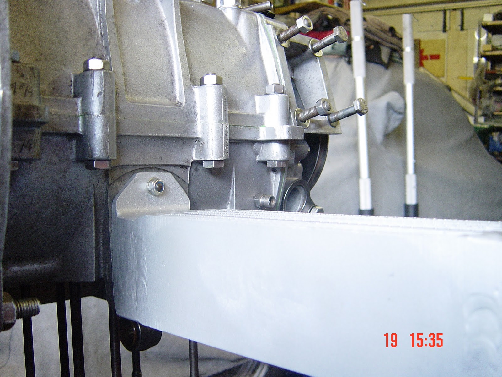
Cylinders held in place by the special bolts made by porsche.

These are hard to find but can be easily re created by cutting a piece of 15mm copper pipe to the correct length and using this as a spacer between the normal cylinder head bolt and the cylinder. Porsche also made these spacer tubes as a special tool. 


Cylinder heads

My cylinder heads have been rebuilt professionally with new valve guides and valves. This is beyond the scope of my blog as it is specialised work.

If you are reusing your cylinder heads get a magnetic probe and check every one of the 8 holes in your head in case there is an old washer still in place. This is a very common problem. if you feel resistance with the magnet check carefully and prise out any old washers. Do the same for the other side.

Take your 8 push rod tubes and fit the seals to the ends as in the photo below. use a little STP/oil mix or some assembly grease on the seals and on the push rod tube ends.


Push rod seal in place, Bevelled edge outwards.

Having fitted all the seals to the push rod tubes, find the 2 air deflector plates as shown below. Note that one has a square cut out and one has a round cut-out. The square one goes on the head of the through bolt side and the round one on the acorn nut side of the case.


They are held in place by a spring that fits over one of  the push rod tubes as shown in the photo below.
When fitting the new (don't reuse the old ones) push rod tubes to  the engine, first clean the case area around where each push rod will seal. Then make sure the welded seam (most likely point to leak) on the tube points upwards or vertically and that the longer end of the push rod tube goes into the case and not the cylinder head.


Spring fitted to push rod tube and supporting heat deflector which sits under the cylinders


Another view of the spring and heat deflector plate.

We are now ready to fit the cylinder head. Take the best cylinder head and use this for cylinders 3&4 as this is the hot side of the engine. (left side of engine looking from pulley end) 

Clean the cylinder head mating surface with WD 40 and paper towel and do the same for the cylinder mating surface. Lubricate the push rod holes in the cylinder head with STP/oil mix. 

Check your long cylinder head bolts have had the old "O" ring washers removed and fit the new ones from the Gasket Kit. They should sit in the groove under the head of the bolt. The head bolts should have a groove machined into them at the mid point of their shanks. This indicates that they are late head bolts and use washers. Early ones did not have this groove and did not use washers.

You will be using some blue loctite on all the head bolts when fitting them.

Now line up the cylinder head with the engine studs and carefully push it over the studs and down towards the cylinders. You will need to line up the push rod tubes and make sure they fit into their holes before the cylinder head will sit properly. It should now look like the photo below.


Now check each of the 8  bolt holes on the cylinder head to check the studs are visible and long enough to drop a washer over. Take a cylinder head bolt washer and by placing it over a screw driver blade drop it over the engine stud deep in each hole. Repeat until all 8 washers are in place. Check with a screw driver that they are sitting flat by tapping the washer around its circumference. 

The head is then retained by the cylinder head bolts. You will notice that there are 2 different head sizes on the long bolts.


Wide brimmed bolt to left with narrow brimmed to right.

Depending on whether you are using an aluminium rocker stand or a cast iron one the arrangement of these bolts will be different. Have a look at the picture below. this arrangement is for the Aluminium Rocker stand.


We have a (from left to right) a wide brimmed, a narrow brimmed, and then 2 further wide brimmed bolts. 

The arrangement for an cast iron stand would be (left to right) wide brimmed, narrow brimmed, narrow brimmed and then wide brimmed.

Apply some blue loctite to the bolts.

Take a 10mm Allen wrench and snug down the 8 bolts using the following pattern. (10-15lbs max)

6  2  4  8
7  3  1  5

When they are snug, leave this side of the engine and repeat the process to fit the other cylinder head.

We are now ready to torque the bolts to their correct level. Starting on one side and following pattern above torque to 15 ft lbs. Repeat for the other cylinder head. 

Now go back to the original side and torque to 20 ft lbs. Repeat for the other cylinder head.

The factory suggests a final torque to 22 ft lbs although some prefer to go a little higher (25ft lbs)

Finally check the torque of each nut 3 times. 

You have installed the cylinder heads.


10. Fitting the pulley shroud,oil slinger, Pulley seal and oil cooler

Pulley shroud


Pulley shroud is held by two short 6mm long bolts.

There are special 6mm long bolts for holding the pulley shroud. Do not use longer ones. Use two 6mm washers bevelled edges outwards and hand tighten until snug. There are 2 typed of pulley shrouds depending on whether you have the late larger oil pump or the earlier smaller one. 

Pulley seal.

Take the pulley seal from the gasket kit. Get your oil slinger washer.


Oil slinger and pulley seal

You will need the special tool to install this seal. It is available from the main parts dealers and is essential to fit the seal correctly. This is because the seal is indented slightly into the third piece and this tool does this. It is a Porsche tool and not a VW tool.

Clean the sealing surface of the case and the oil slinger with WD 40 and wipe off with kitchen paper.

Coat the sealing surface with a little white grease and also the outer surface of the bearing. 
Put the oil slinger in place first and then put the seal onto the seal installer.


Seal Installer in use.

First use a spanner on the hex nut  nut on the end of the seal installer to screw the tool into the cranshaft. next use a spanner as illustrated above to gently tighten the tool which pushes the seal into place. Dont overtighten it! 
Back off the installer and remove it. You will now see that the seal is recessed into the third piece by about 1/16".

If you have an early engine it may well have a different arrangement. Take a look at the next two photographs. The first shows that the third piece has 5 studs around the end of the crank and no obvious place for the seal. The second photo shows that the seal is installed in a special cover that fits on the 5 studs and is held in place by nuts and washers. Your seal installer will not work for this early arrangement and the seal needs to be pressed into place using a hydraulic press with the correct size plate to press the seal.


Five studs clearly visible around the end of the crank


Seal installed on end plate and coated with flange sealant ready for assembly

Take the paper seal from your gasket set. Make sure it fits over the studs. Coat the gasket surface with a little  flange sealant on the side that mates with the third piece. Do the same on the cover plate. 
Make sure the PULLEY KEY is in place (see later)
Place the cover over the studs with the gasket in place and pop on the washers. Evenly tighten the nuts
and torque to 10-12 ft lbs. Clean off any excess flange sealant.


There is a porsche tool for installing the seal - I have never seen one!


Installing pulley.

Turn the engine over until the slot for the pulley key is vertical. take the pulley key and gently tap into place. 
Take the pulley and lubricate the pulley sealing surface with some stp/oil mix. tap on with palm of hand or rubber hammer. Take the pulley nut and washer and pop on. Get a 30mm socket and start to tighten. (you will need your flywheel lock in place) Tighten it firmly but not to tight as you may want to remove it.

Oil cooler.

Next we will install the oil cooler. I would always recommend fitting a new oil cooler. The ones available now have 8mm studs and thee earlier engines only had 6mm holes so the 2 holes will need to be drilled out to 8mm. 
Carefully remove the blanking pieces from the base of the oil cooler or you won`t get any cooling!
Take the 2 seals from your gasket set and lubricate both sides with stp/oil mix and rhen place onto the holes as in the photo below. Note that the stud is 6mm, I believe you can get a step stud to replace it with to make it 8mm. (thanks to Gary Koehler for info).


Seals in place ready for oil cooler to be fitted.

Put a little stp/oil mix on the bottom of the oil cooler where the seals meet it. 

I like to use 13mm captive nuts for bolting on the oil cooler but if you want originality use some red loctite to ensure they do not come loose. Pop the cooler into place and use two 13mm nuts and small washers and hand tighten them. Use a 6mm washer and 10mm nut on the stud. Again I prefer a captive nut but if you use the original then use red loctite. Some people double nut this stud to ensure it does not loosen.

Tighten the 3 nuts evenly alternating between nuts so that the oil cooler does not twist. Do not over tighten or you can crack the oil cooler stand - a disaster!


Cooler in place with 10mm nylock captive nut.


Saturday 8 October 2011

9. Fitting the oil pump drive, bypass and pressure release valves.

We  are now going to fit the oil pump drive.
There are 2 different size oil pumps. pre 1960 it was a small pump and post 1960 a larger pump.
Both sizes of gasket are provided in the kit. Choose the correct size of gasket and make sure the surface of the pump and third part are clean. Use some assembly grease on the gears.


Oil pump assembly. Check the drive key (red arrow) is in good condition and replace if not.


Gears in place in third piece and coated with white assembly grease (early 4 stud small pump).

Fit the correct gasket - there is only one correct way for the gasket to fit so make sure it is lined up properly and fits over the studs. No flange sealant is required and as you rotate the flywheel push the pump onto the studs until the key locates in to the end of the cam and the pump sits flush.
The later pumps are held in place by one long bolt and 3 nuts. Use red loctite on the nuts and threads of long bolt which goes in the bottom left hole. The earlier small pumps had four studs.
Pop on the washers and tighten evenly starting with the bolt on large pumps.  These should be torqued to 10 ft lbs. Turn the engine occasionally awhile tightening the nuts to make sure nothing is binding.

Installing the oil pressure relief and bypass valves.


Oil pressure relief / bypass valves.

There are 3 different set-ups for the valves.

Up to mid 1957

Early engines to the mid 1957 period had just one combined relief/bypass valve. The spring of this one should have 15 turns. Fits into the third piece as in picture below.


The arrow points to the valve position in the third piece

Mid 57 to 1963 

These engines have one relief valve and one bypass valve. Superficially they look the same but the springs are different. 
The oil pressure relief valve is placed in the left case half pointing horizontally and the spring is made of thicker wire. It generally has about 13 coils.

The oil bypass valve fits in the third piece similar to the earlier engines and has a thinner spring with about 17 coils or turns on the spring. It is also shorter.
Do not get them mixed up!

Post 1963 

Both the relief valve and the bypass valve are now identical and so are interchangeable. Use the best plunger for the oil pressure relief valve in the left hand case.

Installing


Take the copper washer / "O" ring from you gasket set.  Make sure the seam which is on the face of the  washer is facing away from the case and towards the head of the threaded nut..

Clean out the case passageways with WD 40.

Clean the parts with WD 40 and then put a little engine oil onto the spring and plunger. Put into position and tighten up with a large screwdriver.

Give it a final tighten with a vice grip. Use an old cloth to stop the jaws damaging the head of the bolt.


Oil pressure relief valve and bypass valves on a post 1963 engine. They are identical and by this stage were interchangeable. Not so for earlier engines.

Seam on copper washer  / "O" ring should face towards the head of the bolt.

Thursday 6 October 2011

8. Fitting the third piece.

We will now move on to fitting the third piece of the engine case.

Make sure the third piece is clean. First we will install the number 4 bearing into the case, the bearing is held by a retaining bolt. Take the third piece and screw in the bolt until its end is just visible inside the hole for the bearing in the third piece.


Bearing retaining bolt shown above where the bearing goes.


Bolt end just protruding at top of picture.


Bearing with guide groove and hole for retaining bolt to fit.

Coat the bearing surface with WD40 and a little engine oil and do the same in the case.
Line up the bearing and use the old bearing as a drift to tap in the new bearing. Try and keep the bearing even and drive in until flush with the case but no further. You should now be able to tighten the retaining screw without resistance. If there is resistance remove the bolt and check with a torch whether the hole in the bearing is lined up correctly.

We are now going to fit the oil pressure line which is the metal tube which is shown on the right hand side of the case in the picture below.


Oil pressure line fitted with barrel washers with openings correctly aligned

It is on the right hand side of the third piece and has two red rubber barrel shaped seals, one on each end.
Take the new ones out of your gasket kit and dip the ends of the oil pressure line in some oil and put one red barrel seal on each end. As can be seen from the photo the line has an "S" shaped end that curls around one of the oil lines on the case. The barrel seals have to be installed correctly with the opening of the one nearest the top of the third piece being visible and in the seal at the bottom, the hole is face downwards as shown in the photos. 
NB some early engines did not have this oil pressure line.

Next we will install the oil seals that fit into the third piece and  seal with the main case. They can either be fitted to the main case end or the third piece end. There are different numbers and arrangements depending on  the year of the engine.

I have illustrated 2 different arrangements in the photos below.


Late engine  after 1963 or so had an extra oil pick-up circled in blue. This used a different "O" ring seal which is in the gasket kit. The 2 larger and one smaller seals are circled in red.


Early case with 2 larger and one smaller seals, (circled)

Coat the seals with oil/stp mix and put into place. Now get out your paper gasket from the gasket set. there will be 3 different types. Choose the correct gasket for your engine and make sure it fits. if it is a little tight it can be soaked in warm water for a 10 minutes to soften it.
Apply Wurth flange sealant to the bearing surface of the engine and the third piece. Use a spatula to spread to a thin layer.
Carefully line up the gasket and fit over studs trying not to tear it! 
Give the crank bearing area a final clean and coat the area with oil/stp mix. Also apply this mix to the Crank gears and the cam gears. Turn the flywheel and repeat the process. You can use engine grease if you plan to store the engine for a long time.

Distributor Drive installation.


There are 2 ways of installing the distributor drive. The Maestro describes the approach where the drive is fitted before final fitting of the third piece. The second approach is where it is fitted after the third piece has been fitted.

Method 1.

Put the distributor drive into the case via the distributor drive hole before installing third piece. We now take the distributor drive and clean it off.  Lubricate it with your STP/oil mix and remembering to install the washer, put it into the distributor drive hole at the top of the case and pop it into position making sure it turns freely. Do not forget the washer at the base.

Look carefully at the top of the distributor drive. It has a groove that is offset.


The distributor drive shaft has a groove that is offset towards the blue side

Make sure that the narrow side of the distributor drive is facing towards the rear of the engine (pulley end) and that the slot is parallel with the mating surface of the engine. Then rotate it 45 degrees or 1/8 turn anticlockwise. This is then the correct position for fitting the third piece. 


Distributor drive shaft in starting position with narrow side facing rear and slot parallel to mating face of third piece.(blue arrows)  It is then rotated 45 degrees anticlockwise. 

We now have to ensure the engine is at top dead centre. 
Place your finger in the hole for the intake cam follower for number 1 cylinder. this is found at the front right of the engine.


Intake cam follower hole - pop your finger in and rotate flywheel clockwise.

Pop your finger in the hole and rotate the engine clockwise until you feel the intake cam follower moving your finger outwards. Keep turning until the motion of the cam follower starts to reverse or goes back the other way. At this point you will find that the rod of number one cylinder (the cylinder above the hole) will be at bottom dead centre. If it is at bottom dead centre it will be low in the hole, so continue to rotate the engine until the rod comes out to its maximum and this will be top dead centre. Make sure it is out as far as possible by gently rotating the flywheel back and forth. This is now top dead centre on the compression stroke.

Method 2

Fit the third piece as below.
Get the engine at top dead centre on number one cylinder as before.
Using the special tool to clamp the distributor drive. This is a VW tool and can be obtained from most VW/Porsche parts vendors.


Distributor drive puller next to drive


Distributor drive puller attached to drive.

Take a long bladed screwdriver and feed the distributor drive washer onto the blade. Hold it carefully close to the handle and put the blade of the screwdriver into the distributor drive hole in the third piece. Look closely to check the screwdriver blade is touching the hole deep in the third piece where the drive sits and when ready release the washer so it slides down the screwdriver blade and onto the top of this hole. The washer can be centralised by moving it gently with the screwdriver. You are now ready to drop the distributor drive into the hole using the tool. 
Make sure the cut out is parallel with the join in the case and that the narrow side faces the rear. Guide the distributor drive down the hole and through the washer until it sits in place. Release the tool making sure you do not rotate the drive and check the groove is parallel with the case join and the narrow side faces the rear (pulley end). This is now the correct position

Fitting the third piece.

Make sure oil seals line up and fit the third piece to the main case, carefully feeding over the studs and tap on with the palm of your hand.
If you now look down the distributor drive hole the slot in the distributor drive should be parallel with the join in the case where the third piece meets the main case.

Take the special 8mm spring washers (they have a smaller outside diameter than normal) and the 12mm nuts and use the best ones either side of generator stand and to the left of distributor hole as these are most visible.

There are 11 nuts and make sure the logos are on the outside. tighten down using a 12mm socket, starting in the middle and working around. check the crank rotates freely. 

Take your torque wrench and torque to 17 ft lbs (15-18 in workshop manual).

Torque each nut 3 times.

You have now fitted the third piece and set up the distributor drive.